Duplexer Tuning using the Amtronix SW2012N Return Loss Bridge
The Amtronix SW2012N Return Loss Bridge can be a valuable aid in duplexer tuning. The pass section of a duplexer will be properly tuned when there is maximum return loss (minimum SWR) from the transmitter to the antenna and from the antenna to the receiver. Manufacturers recommend NOT to use RF power to tune a duplexer. RF Power applied to an out of tune duplexer could cause a rapid increase in temperature and damage the unit.
There are several different types of duplexers including "reject", "pass" and "pass / reject". A reject duplexer has a receive section (2 cavaties) that are tuned to reject the transmit frequency and a transmit section (2 cavaties) tuned to reject the receive frequency. The "Pass" duplexer does the opposite tuning the transmit section to pass the transmit frequency and the receive section to pass the receive frequency. A higher quality model is the "Pass / Reject". This duplexer has both pass and reject properties in both sections.
The Pass / Reject Duplexer can be tuned by using a return loss bridge to tune the Rx and Tx sections for maximum return loss at their pass frequencies. To tune this duplexer, connect the Tx port to the return loss bridge DUT (device under test) Port. Connect a 50 ohm load to the antenna port. Adjust the duplexer main tuning plunger for maximum RL (return loss). TX RX Systems indicates the pass band will be 15 dB or more. The rejection notch is tuned after the pass notch. The rejection notch is not tuned wit the return loss bridge but with a tracking generator or similar means to measure maximum rejection of the unwanted frequency. TX RX Systems has excellent instructions for tuning their 6.625" duplexer. **The HP 8920A/B can be used as the Spectrum Analyzer / Tracking Generator and the Amtronix SW2012N as the return loss bridge. There is a section in the Agilent / HP 8920B Applications Manual on duplexer tuning (Cavity Tuning and insertion loss-page 222): Agilent / HP 8920B Applications Manual
The following is the instructions for tuning the TX RX Systems 6.625 Pass Reject duplexer:
Due to the sensitivity of the adjustments, it is strongly recommended that the proper equipment
be used when tuning the individual filters, otherwise the filter should be sent to the factory or an
authorized
representative for retuning. The following equipment or its equivalent
is
recommended in order to properly perform the tuning adjustments for the
Vari-Notch duplexer.
1.
IFR-2975 spectrum
analyzer with optional tracking generator installed. **(HP 8920A/B,
8924C, E8285A, 8935 can be substituted for Aeroflex -IFR 2975)
2. 5/32" hex wrench.
3. Double shielded coaxial cable test leads (RG214).
4. 50 ohm load with at least -35 dB return loss (1.10:1 VSWR).
5. Female union (UG29-N or UG914-BNC).
6. Return
Loss Bridge (Eagle model#
RLB150N3A). ** (Amtronix SW2012N can be substituted for RLB)
7. Insulated tuning tool (TX RX Systems Inc. part# 95-00-01).
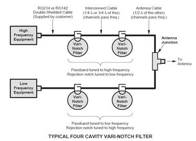
Figure
1:
Block diagram of a typical four-cavity Vari-Notch
Duplexer (6.625" diameter cavities)
Tuning
Procedure
Tuning of the filter requires adjustment of the pass band and the rejection notch. The pass band
is adjusted while observing the return loss response and the rejection notch is adjusted by
monitoring the output of a tracking generator after it passes through the filter. All Vari-Notch filters should be temporarily removed from the system and tuned on the bench using test instrumentation only. Do not adjust the filters while they are under transmitting power. To insure
proper tuning of the 6.625" Vari-Notch filter, all adjustments should be performed in the following
order:
1. Rough tune the pass band.
2. Rough tune the rejection notch.
3. Final tune the pass band.
4. Final
tune the
rejection notch, always the last adjustment made.
WARNING
-
Tuning
while
under
transmit
power
can result in
damage to the duplexer.
PASS
BAND
The peak of the pass band will correspond very closely to the point of minimum reflected energy
from the filter and maximum forward power through it. A transmitter connected to the filter will
operate
best when the
reflected energy is lowest, therefore the return loss response will be
used to
set the pass band. The pass band can be checked and adjusted using the
following procedure.
Checking
the
pass
band
1. A zero reference for return loss must be established at the IFR-2975 prior to checking the
pass band frequency, this is done by connecting the return loss bridge to the
analyzer / generator as shown in figure 3.
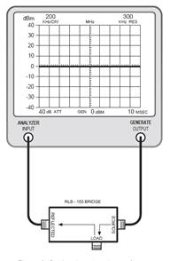
Figure 3: Setting the return loss reference
2. Set-up
the
analyzer / generator for the desired frequency (center of display) and
for a
vertical
scale of 10 dB/div.
3. Do not connect the return loss bridge (RLB) to the cavity, leave the "load" port on the bridge
open. This will supply the maximum amount of reflected energy to the analyzer input.
4. Insure that the IFR-2975 menus are set as follows:
DISPLAY - line
MODE - live
FILTER - none
SETUP - 50 ohm/dBm/gen1
5. The
flat line
across the screen is the return loss curve. Select the "MODE" main
menu item and
then choose the "STORE
"
command.
6. Next select the "DISPLAY" main menu item and choose the "REFERENCE" command.
This will cause the stored value to be displayed at the center of the screen as the 0 dBm
reference value.
7. Connect the "DUT" port on the SW2012N RLB to the input of the loop plate, make sure the output of the
loop plate is connected to a 50 ohm load, refer to figure 4.
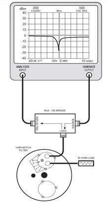
Figure
4:
Checking the pass band
The display will now present the return loss curve for the 6.625" Vari-Notch filter being
measured.
The pass band is that frequency range over which the return loss is 15 dB or greater.
Adjusting
the
pass
band
Set the tuning rod at its mid-point. Adjust the pass band by setting the peak
(maximum negative value) of the return loss curve at the desired pass band frequency
(should be the center-vertical graticule line on the IFR-2975's display).
Refer to
figure 4.
The resonant frequency is adjusted by using the coarse tuning rod, which is a sliding adjustment
(invar
rod) that
rapidly tunes the response curve across the frequency range of the
filter.
Resonant frequency is increased by pulling the rod out of the cavity
and is
decreased by pushing the rod into the cavity.
Cavity
Tuning
Tip
When tuning a cavity that has been in service for some time it is not unusual to find the main tuning rod hard to move in or out. This occurs because TX RX Systems Inc. uses construction techniques borrowed from microwave technology that provide large area contact surfaces on our tuning probes. These silver plated surfaces will actually form pressure welds which maintain excellent conductivity. The pressure weld develops over time and must be broken in order for the tuning rod to move. This is easily accomplished by gently tapping the tuning rod with a plastic screwdriver handle or small hammer so it moves into the cavity. The pressure weld will be broken
with no
damage to the
cavity. Once the desired response is obtained using the coarse and fine
tuning
rods, they are "locked" into place. The coarse rod is secured by
tightening the 10-32 cap screw and the fine tuning rod is held in place
by
tightening the knurled thumb nut.
Failure
to
lock
the
tuning
rods will cause
a loss of
temperature compensation and detuning of the cavity.
REJECTION
NOTCH
The
rejection notch
will track with the tuning of the pass band and therefore should be the
last
adjustment made to the 6.625" Vari-Notch filter. The rejection notch is
adjusted by changing the amount of capacitance in the loop assembly.
The
capacitor is variable and is either an air-plate or tubular piston type
depending
upon the frequency range of the filter. The air-plate type has a red
mark
painted on the access barrel and one-half of the adjusting screw, when
the red
marks line up the maximum capacitance is achieved. On UHF models (400
MHz and
over) the capacitor access barrel is omitted and a 10-32 inch screw
must then
be removed from the loop plate assembly to gain access to the piston
trimmer
under the plate.
Checking the rejection notch
1. The rejection notch is checked by connecting the tracking generator to the input of the cavity
filter while the spectrum analyzer is connected to the output, as illustrated in figure 5.
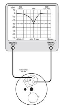
Figure 5: Checking the rejection notch
2. Insure that the IFR-2975 menus are set as follows:
DISPLAY - line
MODE - live
FILTER – none
SETUP - 50 ohm/dBm/gen1.
Adjusting the rejection notch
The notch is adjusted by turning the variable capacitor. Because of the filters sensitivity to tool
contact,
an insulated
tuning tool must be used to make the adjustment.
FINE
TUNING
THE
CHANNELS
Once all of the individual filters have been tuned, each of the channels as a whole must be fine
tuned. First the pass band for both channels and then the rejection notches. The following is a step by step procedure for fine tuning the channels and completes the re-tuning of the duplexer.
1. Reassemble the duplexer by reinstalling the cavities and interconnect cables in their original
locations.
2. The pass band for the channels are fine tuned first, in a manner very similar to tuning a single
cavity.
3. A zero reference for return loss must be established at the IFR-2975. Connect the RLB to the
analyzer / generator as shown in figure 3.
4. Set-up the analyzer / generator to the desired frequency (center of display) and for a vertical
scale of 10 dB/div.
5. Do not connect the RLB to the duplexer at this time; leave the "load" port on the bridge open.
This will supply the maximum amount of reflected energy to the analyzer input.
6. Insure that the IFR-2975 menus are set as follows:
DISPLAY - line
MODE - live
FILTER - none
SETUP - 50 ohm/dBm/gen1
7. The flat line across the screen is the return loss curve. Select the "MODE" main menu item and
then choose the "STORE " command.
8. Next select the "DISPLAY" main menu item and choose the "REFERENCE" command.
This will cause the stored value to be displayed at the center of the screen as the 0 dB
reference value.
9. Connect the "load" port on the RLB to the equipment port of the channel to be fine tuned.
Terminate the duplexer’s antenna connector with the 50 ohm load. The equipment port of
the remaining duplexer channel is left disconnected, refer to figure 6.
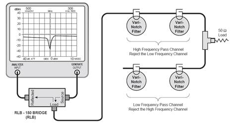
Figure
6:
Equipment setup for fine tuning the pass band of each
channel
10. The display will now present the combined return loss curve for all of the cavities in the
channel. The channels pass band is that frequency range over which the return loss is
15
dB
or
greater.
11. Fine tune the pass band for the entire channel (for maximum return loss) by gently adjusting
the positions of the fine tuning rods (coarse rods if needed) moving between cavities as
required. Once the desired response is obtained "lock" the tuning rods into place by
tightening the 1/4" shaft lock nuts and the knurled thumb nuts on each filter.
12. Move the cable from the RLB's "DUT" port to the equipment port of the other channel. This
will allow the remaining duplexer channel to be fine tuned. Reset the analyzer / generator
center frequency. Repeat steps 10 and 11.
13. The rejection notch for each of the channels must be fine tuned next.
14. Terminate the antenna connector with a 50 ohm load. Connect the output of the tracking
generator to the equipment port of one of the duplexer channels and the spectrum analyzer
input to the equipment port of the remaining channel as shown in figure 7.
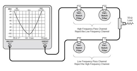
Figure
7:
Equipment setup for fine tuning the rejection notch of
each channel
15. Set-up the analyzer / generator to sweep across the rejection notch frequency of the
channel being tuned. The center of the display should be set to the desired center frequency
of the rejection notch being adjusted. Set the vertical scale of the analyzer / generator to
10 dB/div. Keep in mind that the high frequency channel has its rejection notch set to reject
the low frequency signal and vice-versa for
the rejection notch of the low frequency channel.
16. Insure that the IFR-2975 menus are set as follows:
DISPLAY - line
MODE - live
FILTER - none
SETUP - 50 ohm/dBm/gen1
17. Set the analyzers attenuation control so that the 0 dBm level is at the top of the display.
The display will now show most of the rejection notch. Using the analyzer's attenuation
control adjust the amount of attenuation so that the "peak" or lowest value on the rejection
notch is displayed.
18. The cavities rejection notches are adjusted (for maximum rejection) by gently turning the
variable capacitors in the loop plate assemblies. Move between filters as needed.
Because of the filters sensitivity to tool contact, an insulated tuning tool must be used to
make the adjustment.
19. Adjust the rejection notch of the remaining cavities by changing the sweep frequency of
the analyzer / generator to match the new rejection notch frequency. The equipment stays
connected
as
it
is.
20. Repeat step 17 and 18 for the remaining channel.
(cables and equipment stay connected where they are).
21. With the tuning completed, reconnect the equipment cables and antenna feed line.
Test
the system for proper operation.