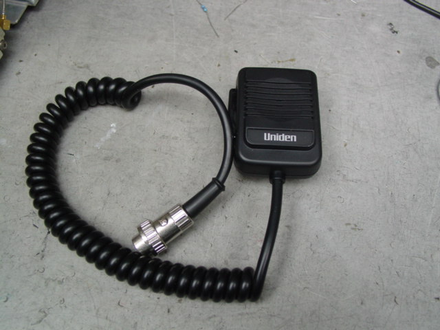
The original 8920 ceramic element microphones are scarce. Most all new microphones have an electric-condenser element that is not compatible with the hp8920. Here is a DIY microphone project that works well for your HP8920A/B 8921A unit. The Uniden MK393 Microphone was chosen because of its compact size and low cost. A switchcraft 05CL5MX mic connector is needed to fit the mic connector on HP 8920 units. This project involves adding a 33uF/50V coupling / blocking capicator, re-wiring the Uniden microphone, adding a different connector to the mic cord and modifying the 8920 motherboard by cutting a trace and adding a 15K ohm resistor. This modification to the 8920 will allow either the Uniden or the OEM - HP mic to be used. The 15 K ohm resistor and 33uf cap values are not critical and can be substituted with anything close. You will need the following parts: Uniden MK393 Microphone ( a google search will fine these for $15 - $30), Switchcraft 05CL5MX connector (Mouser PN 502-05CL5MX), a 33uf/50V capacitor, a 15K ohm resistor and some heat shrink tubing. Note: the Switchcraft 05CL5MX, 5 conductor connector works just fine with the hp8920 - 8 pin mic connector because the extra contacts are unused. Presently, these parts will cost about $30.-$40. After gathering the parts, the first step is to re-wire the Uniden MK393 Mic as follows:
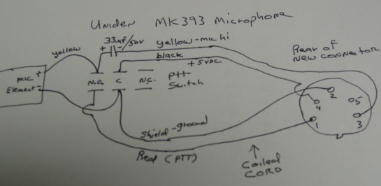
The idea here is to use one side of the DPDT, PTT switch to supply 5V to the mic element and the other side to connect the mic PTT to the mic ground / shield. The 33uF / 50V Cap is to couple the mic audio and block the DC voltage to the 8920 Mic Hi input. The 15K resistor added to the 8920 motherboard supplies voltage to the mic element. Remove the 3 phillips screws from the rear of the Uniden MK393 Mic, remove the rear cover and the PTT switch plastic push lever. Use the crude drawings above for reference. The Mic Hi or yellow wire will be on one side of the PTT switch, the (+) side of the 33uF is to be soldered to the Mic Hi on the switch, the (- ) side of the 33uF gets soldered to the yellow wire of the mic cord. The black wire gets moved to the middle terminal of the switch so it connects to the Mic Hi during a PTT. The black wire will supply +5VDC to the mic hi of the mic element through the PTT switch. The white wire from the mic element is connected to the center of the other side of the switch as well as the shield of the mic cord. The red PTT wire is connected to the other terminal of the PTT switch so the shield (ground) gets connected to the PTT red lead during a PTT. Use heat shrink tubing as needed. Carefully fit the 33uF cap into some empty space in the Mic. Re-assemble the mic using caution not to short or damage wires or components. Remove / unsolder the 4 pin mic connector that came with the MK393 Mic. Install the Switchcraft 05CL5MX as follows: Add the Switchcraft connector shell to the coiled cord. Neatly solder the red wire (PTT) to pin#1, shield (mic and PTT ground) to pin 2, yellow (mic hi) to pin 3, black (+5VDC) wire to pin 4. Re-assemble the connector. This completes the microphone wiring.
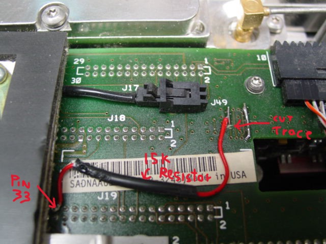
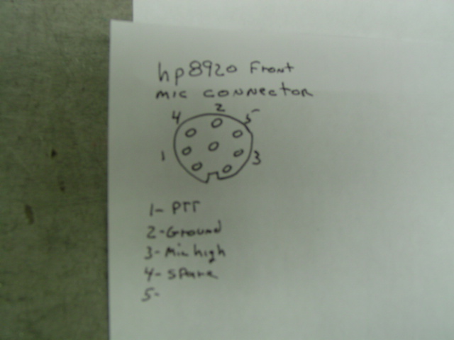
Remove the HP 8920 case. A trace is cut and resistor added to the 8920 motherboard to supply 5VDC to the microphone element. The original 8920 microphones used a un-powered ceramic element. Most all new microphones use an electric - condenser type element that requires power. This motherboard modification will allow either the newer or older type microphones to be used. The unused pin#4 on the 8920 mic connector will be used to supply 5V to the new mic. On the motherboard bottom, locate the trace near the "J49" speaker connector as pictured. Cut the trace as pictured. Connect a 15 K ohm resistor from J19-pin33 to the side of the cut trace nearest the J49 connector and use heat shrink as needed. Note : J19 is the motherboard connector for the Modulation Distribution Board and pin 33 is the +5VDC supply. To test the microphone, go to the Audio Analyzer Screen and select "Mic Mod" for the "AF ANL IN" field and turn up the volume. To see the audio on the scope, select "Scope" on the lower right "Analog" field.
HP 8924C Modification
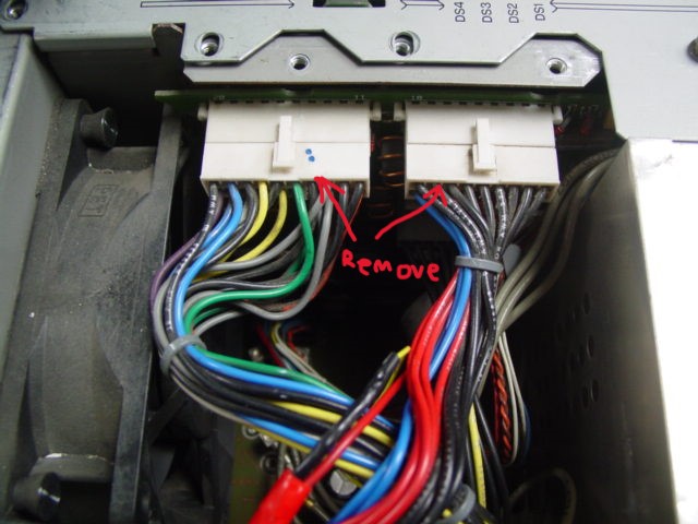
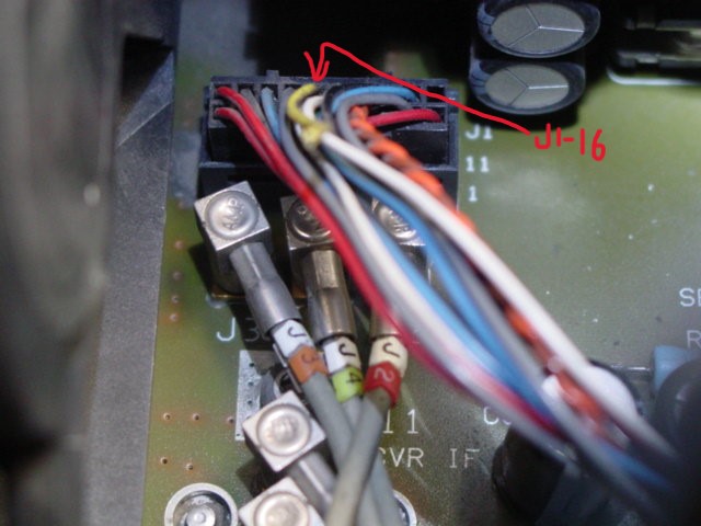
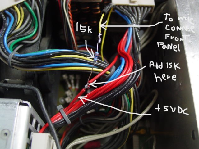
On the HP 8924C, the modification to add +5VDC to the mic connector is different. Remove the 8924 cover assy, remove the power supply shield / cover inside. To get access to the motherboard, remove the (2) power supply to regulator board connectors as in figure 1. Locate J1 connector near the fan. Remove the connector. Locate J1-pin 16 (yellow wire) and cut it about 1" from the connector. Tape or add heat shrink to the yellow wire that goes to the J1 connector. The other side of the yellow wire goes to the front Mic connector - pin#4. Add the 15K ohm resistor from the +5 VDC wire on the power supply output to the yellow wire that goes to the front mic connector. Note: The top red wires on the power supply top connector all have +5 VDC. Tape and heat shrink as necessary. Re-install J1 connector, the 2 power supply connectors and the power supply cover. To test the microphone, go to the Audio Analyzer Screen and select "Mic Mod" for the "AF ANL IN" field and turn up the volume. To see the audio on the scope, select "Scope" on the lower right "Analog" field.
To use this or any mic with the 8920 /8924 units, go to the RF Generate screen, turn off the 1000 Hz tone on the audio frequency 1 column, set the 'Mod In To" field to FM and 4 KHz (or 2 KHz for narrow band). ( or you can set it to AM) You can then set your frequency, RF level out, CTCSS (PL) or (CDCSS) DPL tone if wanted on encoder screen, press TX test, set receive frequency. With an antenna connected to the RF I/O port (or 2 antennas connected to the duplex and antenna ports), the 8920 unit can now function as a transceiver. It will receive until you press the mic PTT key, then it will switch to TX test (generate). Once you set this up, you can save the setup to memory. This microphone project and 8920 modification has been tested and works. Amtronix Instruments assumes no liability for any mishaps or problems that may be encountered.