If your using an HP / Agilent 8935 or E6380A (81A) Test set, the RF Software Tools is included in the units firmware. If your using an HP 8920A, HP 8920B, HP 8924C or HP E8285A, you need to install the software. To install your HP 11807E opt 100 software, after your unit is turned on and booted up, install the PCMCIA card into the card slot. Press the "Test" key. Move the curser to "procedure location" and highlight it, then select "card". Move the curser to "procedure filename" and select "RF Tools". Move the curser to the top right and select "Run Program". The program will take a minute to load then give you several choices.
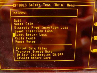
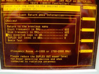
Select "Swept Return Loss". The screen will ask you to enter a start and end frequency to sweep. Enter them then scroll to the upper right and select "Begin Test" (or press the K1 key). The test set will now show a picture of the return loss bridge and cables to demonstrate where the cables go.
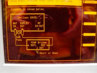
They recommend you add 6 db attenuators to the generate and receive cables at the test set end. This helps assure a good match for each cable to test set connection. This may be unnecessary with most modern service monitors with 50 ohm inputs to the generate and receive ports. This is still recommended it if you want to assure the best accuracy. The picture on the display will tell you to put a short or open on the DUT port. I have good results putting nothing on the DUT port but if you have a short or open connector, I recommend using them. This can increase accuracy at higher frequencies. If you are testing an antenna system and need to use a coax jumper to go from the RLB to the antenna system coax, cal your RLB with the coax jumper connected to the RLB. This will insure you measure the return loss (or swr) at your antenna system coax connector. Follow screen instructions and continue. The test set will now measure the return loss from this worse case load across your frequency range. Do not move your cables from now to the DUT sweep is complete.
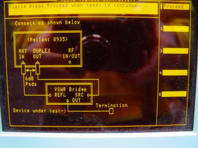
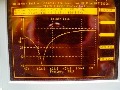
After the "cal", your test set will tell you to add a "Termination" to the DUT port. Now you can add your antenna, coax or test load. Press "Proceed" and in a short time, your unit will provide a nice frequency vs. return loss graph.
You have the option of printing out the screen to a printer or saving the plot to a memory card. If your using a 512K card, there should be room for 200 or more sweeps.
Once you install RF Tools in your test set, it will stay in the test set's memory even if power is removed. From then on, you can use RF Tools by pressing the "Test" key. The RF Tools screen will appear. DO NOT select the "Location / Card" or "Procedure / RF Tools" section. If you do, you will loose the program and need to use the memory card to re-load it. Move the curser and select "Begin Test" and the program will run.
Back to the Return Loss Bridge Page