0.5 - 1500 MHz
Return Loss Bridge
Amtronix Instruments, Inc. Ph
716-763-9104
Amtronix Instruments, Inc. has discontinued the SW2012N Return Loss Bridge, however, Masters Communications is now making them. We have worked with Masters Communications and can report that all specifications including accuracy, directivity and overall quality of their RLB1500 is the same as our SW2012N. The Masters Communications RLB1500 is a direct replacement for the Amtronix SW2012N.

Amtronix Instruments, Inc. has discontinued the SW2012N Return Loss Bridge, however, Masters Communications is now making them. We have worked with Masters Communications and can report that all specifications including accuracy, directivity and overall quality of their RLB1500 is the same as our SW2012N. The Masters Communications RLB1500 is a direct replacement for the Amtronix SW2012N.
Turn your
service monitor or signal generator / signal receiver into an accurate
antenna analyzer. This will provide the same accuracy as antenna
analyzers costing thousands more. The SW2012N is
a
commercial duty
0.5 - 1500 MHz return loss bridge (RLB) for your antenna/feed line
testing. Bridges are individually tested and include a performance
graph. This unit has a 0.5 - 1500 MHz
range and minimum 35 db directivity (40 dB typical). The unit
has high quality type N connectors for all ports and a new
configuration with the input and output ports conveniently on one side.
The new design will withstand 4 watts of accidental power input to the
DUT port. Use your existing rf generator and receiver/power
meter/spectrum analyzer to make accurate measurements.
Please note: This product is being discontinued. We have just a few units left in stock. The SW2012N continues to be an excellent working rugged and dependable product. We originally manufactured this bridge to provide a lower cost alternative that had compairable or superior performance to more expensive units. The profit margin has been slim and for that reason, this product will soon be discontinued. We will continue support should it be necessary. Another company will soon continue the manufacturing of this bridge with some design changes. Their contact information will be posted here as soon as they have the product to sell.
Please note: This product is being discontinued. We have just a few units left in stock. The SW2012N continues to be an excellent working rugged and dependable product. We originally manufactured this bridge to provide a lower cost alternative that had compairable or superior performance to more expensive units. The profit margin has been slim and for that reason, this product will soon be discontinued. We will continue support should it be necessary. Another company will soon continue the manufacturing of this bridge with some design changes. Their contact information will be posted here as soon as they have the product to sell.
The Basics of a Return Loss Bridge
In
simple terms, the return loss bridge is a device used to measure RF
power
reflected from a load or device under test (DUT) when power is sourced
to the
device through the RLB. The return loss bridge has 3 ports. An RF
signal
generator is applied to the input port. The output port provides an RF
signal
to go to a measuring device such as a spectrum analyzer, power meter or
other
device used to measure this signal. The DUT port connects to the device
that
you are testing (antenna, coax, etc.). A signal is generated into the
input
port. The RLB applies this signal to the DUT. The
DUT
will
reflect
a
portion
of
the
signal
that
it
receives
(due
to
impedance
mismatch).
This
RF
signal
appears
at
the
output
port.
The
closer
your DUT impedance is to 50 ohms, the lesser the signal will be
at the
output port. A perfect 50-Ohm DUT will have no reflected power so a
perfect RLB
will have no output signal at its output port (infinite return loss).
If a
non-50-Ohm load is at the DUT port, there will be an RF signal at the
output
port. The extreme cases are for the DUT to be a short or an open
connection.
This will cause maximum reflected power and, therefore, maximum signal
at the
RLB output port. Return loss is measured from the worse case (short or
open) with 100% power reflected. It's the difference amount in dB of
the
reflected
signal of your DUT compared to the worst case reflected signal. The
further you
go from "worse case" the better. The higher the return loss number,
the closer the DUT is to 50 ohms. This is somewhat the opposite when
compared
to SWR ( high SWR means high reflected power or poor match) For
example:
with an
open or short connected to the DUT port and an RF signal source
generating into
the RLB input port, let's say we measure the RF power at the RLB output
port to
be -22 dBm. If the open or short were replaced with your load at the
DUT port,
the amount of power at the RLB's output port would then change. If the
output
signal is now measured to be -42 dBm, this would be a return loss of 20
dB. The
amount of reflected power is 20 dB less than the worst case. This is
equal to
an SWR of 1.22:1. If this were an antenna, it would be considered an
excellent
match with about 1% of the power to the antenna reflected. A return
loss of 10
dB would correspond to an SWR of 1.91:1 with 10% of your power
reflected. This
is generally considered a poor match. Most commercial systems want to
see a
return loss of 18 dB or better.
Directivity

SW2012N Return Loss Bridge
Directivity
is
the
measure
of
how well the RLB isolates 2 opposite traveling (foreward and reflected)
signals. As the reflected signal becomes smaller and approaches the
specified value of the RLB directivity, the measurement uncertainty
becomes larger. To get accurate return loss (SWR) measurements, it's
important to have a bridge with directivity of 10 to 20 dB higher than
what you want to measure. The higher
the
directivity, the greater the accuracy the RLB can measure small signal
levels of
reflected power. A perfect 50-Ohm load should have
infinite
return loss, which translates to no output signal from an RLB. If we
could
build a perfect RLB, the output port would show no signal with a
perfect 50-Ohm
load. In the real world, the highest quality RLB would show a return
loss of up
to 50 dB. 50 dB would be pushing the
physical limits because the N connector itself has a tiny amount of
return
loss. This is great, but most techs really don't care about directivity
above
20 dB. A higher quality bridge will have higher directivity than needed
to
provide better accuracy at all levels. The SW2012N has guaranteed
directivity
of 35 dB with typical directivity being
40 dB or better over the 0.4 - 1500 MHz range. A 20 dB
directivity means
that you'll see as little as 1% of reflected power. A directivity of 30
dB is
0.1% and 40 dB is 0.01% ( 1/10000 of worse case reflected power level).
The
SW2012N Return Loss Bridges are individually tested and include a
performance
evaluation graph.
SW2012N Return Loss Bridge
Using your RLB
Many service
monitors have "swept return loss or SWR
programs" built in. When used with a return loss bridge, these programs
provide a frequency vs. return loss graph on your screen. You need 2
cables. One
is from your service monitor output port (RF Source) to the RLB input
port, the
other is from the RLB output to your service monitor's antenna port (RF
Measurement). Your service monitor will poll you to "begin test" with
an open or short connected to the DUT port. It will then have you
connect your
DUT (antenna or coax) to the DUT port. It will then give you a
graph of your DUT performance. There are many
ways to capture and save this graph for later viewing or comparison.
Try not to
move your cables or RLB from the time you start the cal with the open
or short
until after the sweep of your DUT. At higher frequencies, this may
cause errors
in the results.
If
your service monitor does not have a Swept Return Loss Program, you can
still use the
bridge in a manual method. Similar to above, you need to connect a
signal
source to the RLB input, and some device to the RLB output port to
measure the
RLB output. This can be a spectrum analyzer or power meter. Generate a
0-dBm
signal with your source. Set your signal source to the desired
frequency and
measure the RLB output with an open or short connected to the DUT port.
The RLB
output is viewed with your spectrum analyzer or power meter. You can
check one
frequency, several, or sweep up and down and note the signal level(s).
Now
connect your DUT to the DUT port. Observe your power reading on your
spectrum
or power meter. Subtract your original reading from this reading (or
vice versa
with negative numbers) and this is your return loss.
To test your RLB, it's necessary to have a precision 50 ohm termination. This will allow you to sweep your RLB from 1-1500 MHz to make sure its working properly. If your service monitor has a RLB program, you should see return loss vs. frequency similar to the graph on the left below. We offer the Narda 370 BNM, 50 ohm N male termination for testing this RLB. Using your RLB with HP's RF Tools Software
To test your RLB, it's necessary to have a precision 50 ohm termination. This will allow you to sweep your RLB from 1-1500 MHz to make sure its working properly. If your service monitor has a RLB program, you should see return loss vs. frequency similar to the graph on the left below. We offer the Narda 370 BNM, 50 ohm N male termination for testing this RLB. Using your RLB with HP's RF Tools Software
Typical Performance

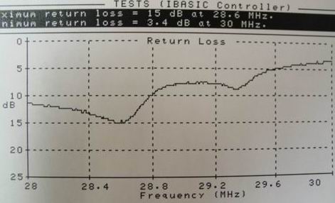
Here is a typical
return loss graph printed from an HP E6380A Service Monitor. The left
graph shows the typical response when sweeping the Narda 50 ohm
precision load. Sweeping to 1000 MHz shows this return loss
bridge is
working properly with a better than 35 dB directivity over this range.
On
the right is a sweep of a 10-meter yagi antenna. At the top, the
maximum return
loss was 15 dB at 28.6 MHz. Generally,
you want to sweep just 1-2 MHz to get the resolution needed to see the
exact resonant frequency as well
as the usable frequency range. The SW2012N can be a valuable tool for
duplexer tuning. See Duplexer Tuning with
the Amtronix SW2012N for details.
The SW2012N was compared to several higher priced units and provided similar results for return losses below 40 dB.
To place an order, call 716-763-9104 or email Amtronix Instruments
Summer Sale !!
SW2012N 0.5-1500MHz RLB (includes performance chart) Specifications............................................$279.00
Narda N male 50 ohm precision test load with chart (35 db).....(these are used / tested)................$ 40.00
24" N male to BNC male RG400 (double shield) cable set.(for input and output connections)...$ 40.00
24" N male to N male RG400 (double shield) cable set..(for input and output connections).........$ 40.00
6 dB BNC to BNC fixed Attenuators (includes 2) for cable end to your equip...........................................$ 35.00
6 dB N male to N female Fixed Attenuators (includes 2) for cable end to your equipment............$ 49.00
SW2012N Kit with cable set, Narda precision load and carry case..................................................................$419.00
SW2012N Kit as above with (2) 6 dB BNC to BNC attenuators...........................................................................$439.00
Huber Suhner 4901.17.A 50 ohm power divider (used for distance to fault measurements)....$165.00
SW2012N Super Kit Includes all above and the Huber Suhner Power Divider.......................................$539.00
UPS Ground Shipping...........................................................................................................................................................................$ FREE
Back to Test Equipment
The SW2012N was compared to several higher priced units and provided similar results for return losses below 40 dB.
| VSWR |
Return Loss |
Power Refl% |
Power Trans% |
| 1.01 |
46.1 |
0.0 |
100 |
| 1.02 |
40.1 |
0.0 |
100 |
| 1.06 |
30.7 |
0.1 |
99.9 |
| 1.10 |
26.7 |
0.2 |
99.8 |
| 1.20 |
20.8 |
0.8 |
99.2 |
| 1.22 |
20.0 |
1.0 |
99.0 |
| 1.30 |
17.7 |
1.7 |
98.3 |
| 1.50 |
14.0 |
4.0 |
96.0 |
| 1.91 |
10.0 |
10.0 |
90.0 |
| 2.0 |
9.5 |
11.1 |
88.9 |
| 3.0 |
6.0 |
25.0 |
75.0 |
| 4.0 |
4.4 |
36.0 |
64.0 |
| 5.0 |
3.5 |
44.4 |
55.6 |
To place an order, call 716-763-9104 or email Amtronix Instruments
Summer Sale !!
SW2012N 0.5-1500MHz RLB (includes performance chart) Specifications............................................$279.00
Narda N male 50 ohm precision test load with chart (35 db).....(these are used / tested)................$ 40.00
24" N male to BNC male RG400 (double shield) cable set.(for input and output connections)...$ 40.00
24" N male to N male RG400 (double shield) cable set..(for input and output connections).........$ 40.00
6 dB BNC to BNC fixed Attenuators (includes 2) for cable end to your equip...........................................$ 35.00
6 dB N male to N female Fixed Attenuators (includes 2) for cable end to your equipment............$ 49.00
SW2012N Kit with cable set, Narda precision load and carry case..................................................................$419.00
SW2012N Kit as above with (2) 6 dB BNC to BNC attenuators...........................................................................$439.00
Huber Suhner 4901.17.A 50 ohm power divider (used for distance to fault measurements)....$165.00
SW2012N Super Kit Includes all above and the Huber Suhner Power Divider.......................................$539.00
UPS Ground Shipping...........................................................................................................................................................................$ FREE
Back to Test Equipment